Not too long ago, I gave my brother a decent Pentium 4 Dell PC. Now that I brought him a monitor, keyboard, and mouse, he decided he wants to use it to run an IRC server. There is a bit of a hiccup, however. The PC can only connect to the network via wired Ethernet. There are not any Ethernet jacks in his room. He already has two laptops; one laptop cannot connect to the Wireless LAN so his other laptop acts as a router between it and the network.
We thought of a number of solutions for this predicament:
- Buy another set of power line Ethernet adapters (~$100)
- Run Ethernet cabling up two stories (A big pain in the ass)
- Buy a switch and continue to use the laptop with WLAN connectivity as the router (~$30)
- Buy a wireless PCI adapter for the PC (~$50)
- Think of something innovative
Since we didn’t want to spend any money, options one, three, and four were out of the question. Additionally, because he is hosting a server, options three and four are not smart choices because they are unreliable.
The only option we had was number five: Think of something innovative. So I did.
I wondered about our options regarding connecting a switch to the network from his room. The only real option we had without running cabling or purchasing expensive power line Ethernet adapters was wireless. I found a Cisco Aironet 1200 series wireless access point laying around (I hadn’t yet used it because I did not have any antennae). I currently have a Cisco Aironet 1200 series wireless access point set up now to serve my house wireless connectivity over 802.11b. There was also a Linksys WRT54GL router lying around still in its box. Don’t ask me where it came from.
I put two and two together and came up with the idea to create a wireless bridge between both Cisco Aironet access points and to use the router to bring all of his devices together in his own network. To save everyone who is in a similar situation time and energy, I will describe the steps I undertook and the problems I encountered while accomplishing this.
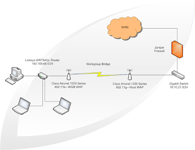
Concept Link to heading
The idea was to create an island of devices that would connect to the network across a wireless bridge. Here is an image to illustrate:
Setting up the new Wireless Access Point Link to heading
To start, I wanted to make sure that I had a factory-fresh WAP. I held down the mode button and plugged in the power cable. The middle LED light on the top of the WAP turned amber in color, and then I released the mode button. This ensured that all the settings were in their default states.
I proceeded to connect my brother’s laptop to the WAP with an Ethernet cable so that I could configure the device. Cisco Aironet 1200 series Wireless Access Points will have all of their wireless radios turned off by default and will only be configurable via Ethernet cable or console cable. I decided the GUI method via Ethernet cable was the easiest route to take to configure the WAP. Depending on the model of the Cisco Aironet 1200 series WAP, the device will either be preconfigured with a static IP 10.0.0.1/8 or automatically get IP information via DHCP.
I continued to configure the device by statically setting my brother’s Ethernet adapter with IP address 10.0.0.2/8. I pointed Google Chrome to the WAP and logged in using the default credentials:
- Username: Cisco
- Password: Cisco
I therein discovered that this WAP had an 802.11g adapter in it, which is far better than my existing 802.11b WAP. I decided I would swap them.
After logging in, I went to Security -> Admin Access -> Local User List and created a new read/write user for myself. After, I deleted the old user. I also changed the default authentication password. Now that I had relogged in, I went to Express Set-Up. I picked a system name, entered my chosen SSID, and selected Apply. I then went to Network Interfaces -> Radio0-802.11G -> Settings. I enabled the radio and ensured that the role was set to Access Point Root. Down the page, there is an option to enable Reliable Multicast to WGB. Make sure this is enabled. Per Cisco, this option will treat the WAP on the isolated network as an infrastructure device to ensure multicast integrity. After this, hitting apply put everything into effect. The radio, though enabled, will still appear to be disabled. This is because the SSID still needs to be configured. I selected Security -> SSID Manager. Here I created my SSID and selected the encryption options. After hitting Apply, there was just one more option I needed to configure. I went back to the Express Set-Up page and changed the Configuration Server Protocol to DHCP. This is because I created a DHCP reservation for this device’s MAC address for management purposes. After this change, the device was inaccessible to me. I swapped it out with the 802.11b WAP and tested. It worked. :-)
Setting up the old Wireless Access Point Link to heading
Now that I configured the 802.11g WAP as the Access Point Root, it was time to setup the wireless bridge. I ran into quite a few problems with this one. Firstly, I set the WAP to factory defaults. Then I had problems trying to get into the management page. The reason for this was because the device is configured for DHCP by default. So, I connected it to the network and looked up its IP address in my DHCP server’s client list. I was able to successfully log in and change the admin account settings and the hostname. I did have a problem configuring the role for the device as a Workgroup Bridge. Every time I tried to select the option, it wouldn’t stick. I could actually only select three of the five roles on this page. I was able to get around this by telnetting into the device (telnet is enabled by default) and running the following commands:
# enable
# configure
(config)# interface dot11radio 0
(config-if)# station-role wgb
The GUI then showed the option selected. I enabled the radio and added the SSID with the same name and encryption settings. (The SSID must be exactly the same on both Wireless Access Points for the Workgroup Bridge to work.) As soon as I hit apply, the device became inaccessible to me. The radio turned on and the WAP was all good to go. There was only one step left.
Setting up the Linksys WRT54GL Link to heading
This was the easiest part. I connected the router to my brother’s laptop with an Ethernet cable. I statically set his Ethernet adapter to IP address 192.168.0.2/24. The default IP address for the Linksys router is 192.168.0.1/24. I used the default credentials to login:
- Username: admin
- Password: 1234
After changing the default password, I turned off the radio, as it was unneeded. I also disabled the firewall on the device because it is unneeded on the trusted network. I set the WAN settings statically to match my network and configured the DHCP settings to lease IPs on a less popular subnet (in case he ever tries to create a tunnel to an outside network, the subnets are unlikely to match). I changed the device mode from Gateway to Router in order to setup the static routes. (Both my Juniper Firewall, which serves as my network’s default gateway, and the Linksys Router support RIP, however I noticed that the routes were never dynamically added over a substantial amount of time, so I created them statically on both devices). Be sure to remember that the network will be accessed across the WAN interface on the Linksys router.
Putting together the pieces Link to heading
After having configured both wireless access points and the router, we plugged everything in. The PC connected to the built-in switch in the router and the router’s Internet port connected to the WAP’s Ethernet port. We tested connectivity between the networks from both ends without any issues. It worked right away.
Though we could have found simpler solutions with little investment to connect my brother’s PC to the network, we learned quite a bit about wireless workgroup bridges, routing, and networking while having a lot of fun!
Post your ideas, comments, suggestions, and questions as a comment if you’d like!
Stay classy, fellow bloggers.